I always want to start an electronic project that build a home automation system but I don’t have much time. Don’t have time is just a bad excuse. So to make thing starts, I start buying electronic components and devices that I need and trying them one by one.
These are the things I have bought:
- A Raspberry Pi model B
- An Arduino starter kits
- GPIO T-Cobbler and cable
- Some Attiny85 mcu – a low power, 8 pins, AVR microprocessor
The basic idea of my home automation system is to create wireless sensor nodes that send data wirelessly to a central server. The sensors’ data will be gathered at central server, processed,  stored in database and will be presented to users via LCD display, HDMI display and website.
Sensors (like reed sensor and temperature sensor) will be connected to Attiny85 and Attiny85 will read data from the sensor and send the data to the server via radio transmitter module using radio wave. These components will form a sensor node.
Raspberry Pi (the central server) will connect to another Attiny85 which will then connect to a radio receiver module. Raspberry Pi will receive data from sensor nodes and the data will then be processed and stored in database.
Before assemble to whole home automation system, I have to test the components out so that I can make sure they can work correctly and they work as what I have expected theoretically the way they should work.
Making electronic project is fun. It takes some time to learn and it makes your hand dirty!
So, what I have done so far?
- I’m able to load the blink project into both Arduino and Attiny85.
- I’m able to make Attiny85 to talk to PC via serial communication.
- I’m able to make Attiny85 to talk to Raspberry Pi via serial communication.
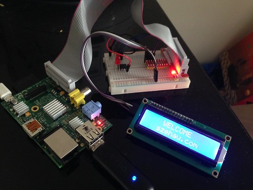
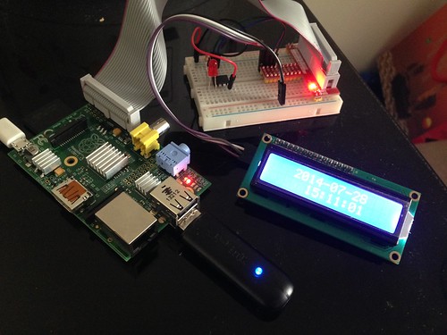
- I’m able to make Raspberry Pi to display text on the LCD 1602 using I2C communication protocol.
The picture below shows the Raspberry Pi output text to the LCD display and at the same time receive data from Attiny85. It takes the whole day to program the LCD driver in Java (ported from Arduino’s LiquidDisplay driver and interface with Pi4J’s I2C library) as there is no existing driver available on the Internet.


One of the major obstacle in writing the drive is that the China’s version of LCD 1602 wires the data cable in the reverse position and it took some time to discover this! Great that it is now working correctly!